
Reference cards have been around forever, they are a common item in our industry. They come in various sizes and shapes and cover a wide variety of topics. From rigging applications to hand signals and from basic math to safety tips. You name it and there is a reference card for it.
Except for hydraulic platform transporters… until now.
This 16 panel Hydraulic Platform Transporter Reference Card is developed by me, Marco J. van Daal, and is applicable for every type of hydraulic platform transporter on the market today, both pull type as well as self propelled modular transporters (SPMT). It has a handy size of 12 cm x 9 cm (4.75 inch x 3.5 inch), it can be easily tucked away with your other reference cards. It is laminated and weather proof and very suitable to be used in the field. Last but not least, it is in both metric as well as imperial units.
This invaluable Hydraulic Platform Transporter Reference Card is available for only USD 19.95

The Works international has entered into a publishing agreement with Industrial Training International or ITI. Clicking the “Buy Now” button will take you to the ITI website for further payment handling. The ITI website will open in a new window, but this window will remain open as well. Once you complete the transaction you can simply close the ITI window and return to The Works international website.
Panel 1 gives an overview of the standard 3-point and 4-point suspension settings. It identifies every hydraulic suspension valve and hydraulic line on the transporter and an easy to understand diagram visualizes the oil flow and the effect on the operation. Furthermore, this panel offers definitions and principle working and highlights terminology. All other panels refer back to this panel 1 for terminology and abbreviations.
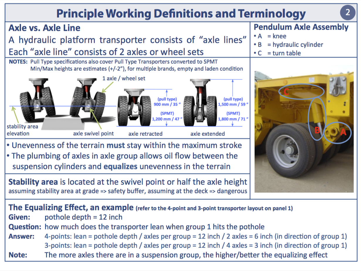
Panel 2 explains the difference between an axle and an axle line. It illustrates the possible movements of such axles with their respective minimum and maximum height to negotiate uneven terrain. A picture clarifies the various components of a pendulum axle assembly. This panel offers a sample calculation of the so-called “equalizing effect” that takes the guessing out of a transport operation.
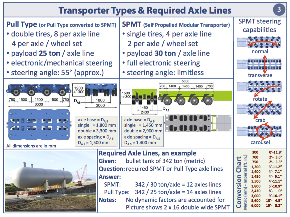
Panel 3 highlights the difference between pull type and self propelled transporters, in terms of steering capabilities, steering angles, tires per axle, payload per axle line, self weight and dimensions. This panel also offers a sample calculation of how to determine the minimum required number of axle lines to carry a certain load. This calculation can be easily applied to your situation.
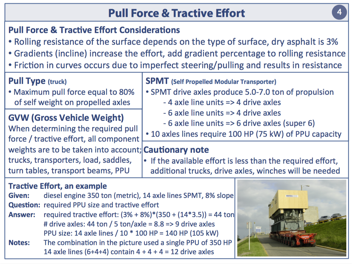
Panel 4 offers an overview of rolling resistance of vehicles and how you can quickly determine the required truck capacity to pull a certain load. Similarly it shows how to figure out how many drive axles an SPMT would need to transport the same load and what the capacity (kW or hp) of the power pack (PPU) needs to be to handle the demand. In case the transport is climbing a gradient it is obvious that the required power increases, the panel provides this as well.
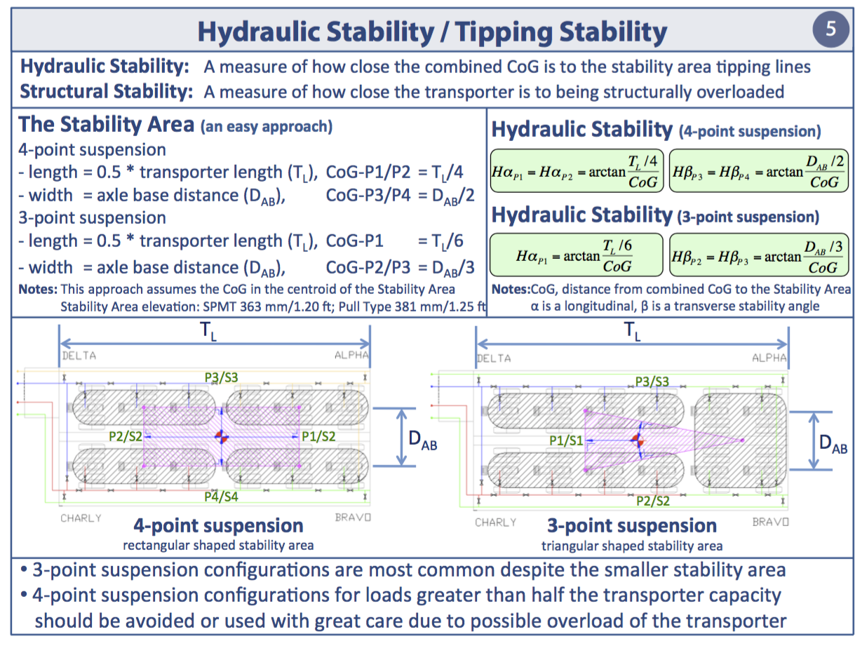
Panel 5 shows a quick and easy calculation on how to determine the hydraulic stability angle of a transport, in a 3-point as well as in a 4-point suspension configuration, with a single formula. The hydraulic stability angle is a measure of how close the combined center of gravity (CoG) is to the tipping lines of the stability area. This gives the crew a better level of comfort when changes in the field take place.
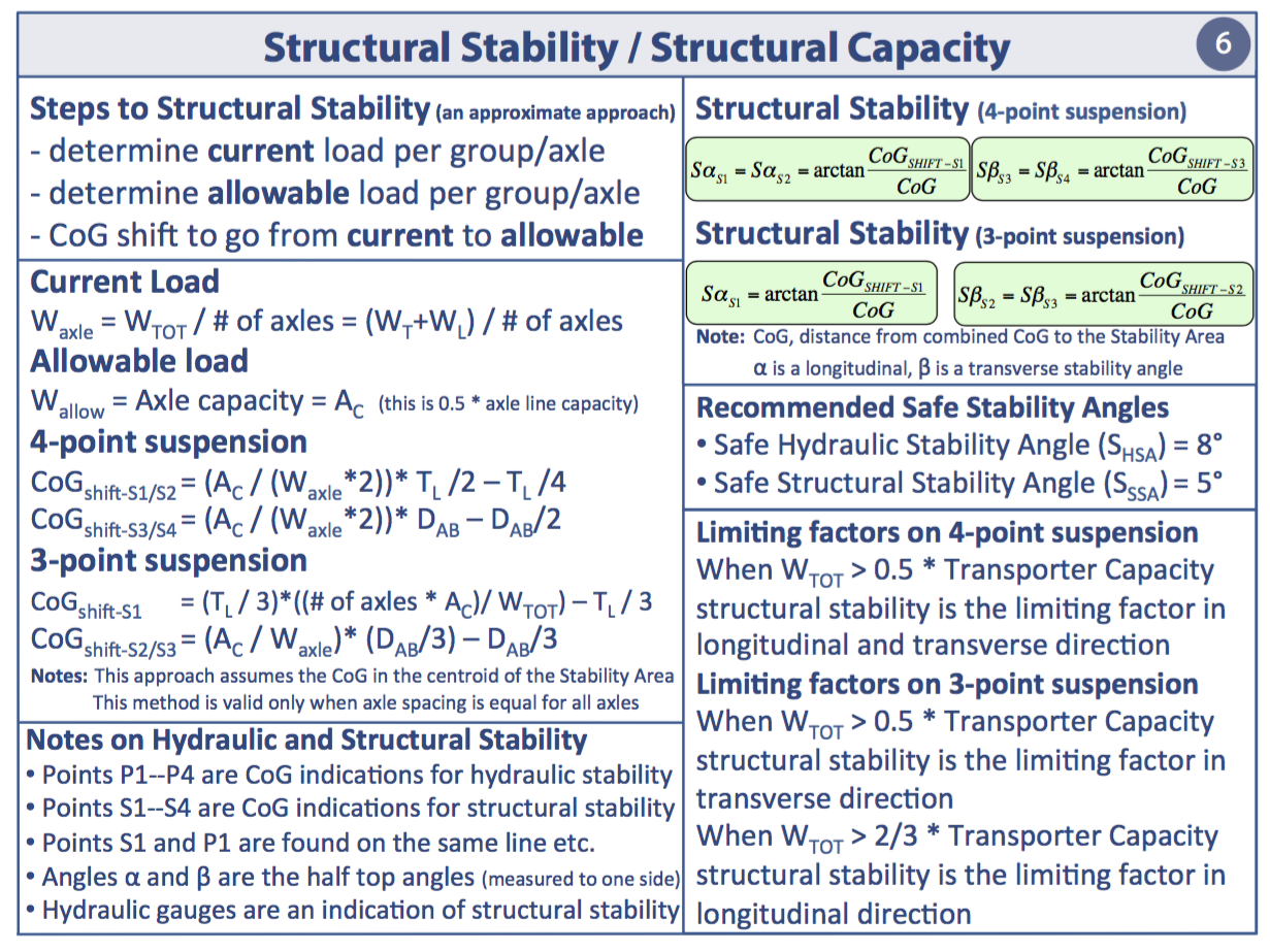
Panel 6 is similar to panel 5 but with the focus on calculating the structural stability angle of a transport, in a 3-point as well as in a 4-point suspension configuration, with a single formula. The structural stability angle is a measure of how close the transporter is to being structurally overloaded. In addition, this panel provides information on the limiting factors on 3-point and 4-point suspension and on the recommended Safe Stability Angles.
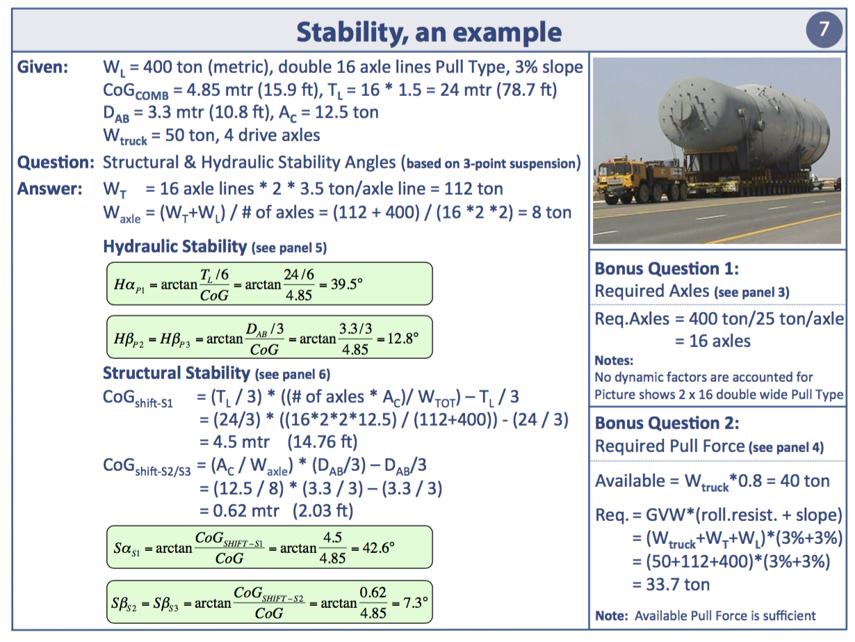
Panel 7 shows a complete hydraulic and structural stability sample calculation based on the information and formulas from the preceding panels. It also calculates the minimum number of requires axle lines given a certain load and the required pull force while going up hill. This panel gives an outline that can be easily adopted to your load.
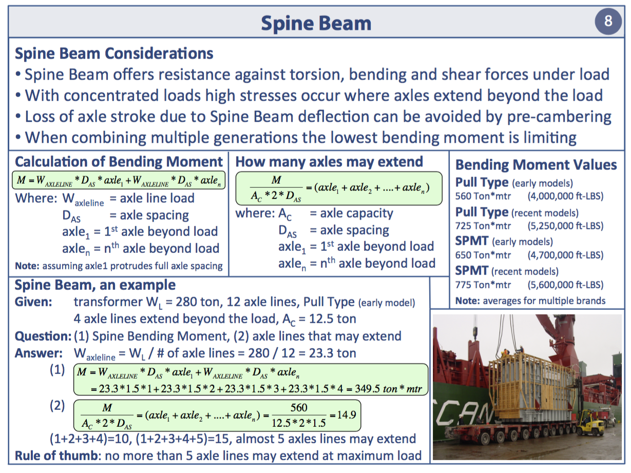
Panel 8 is about the spine beam. The spine beam offers resistance against torsion, bending and shear forces. It is important not to exceed the maximum values of these forces. Specifically with concentrated loads there is a significant risk of spine beam overload if not correctly analyzed. This panel shows how to determine the spine beam bending moment and how many axles may extend beyond the load given the type and approximate age of the transporter model.
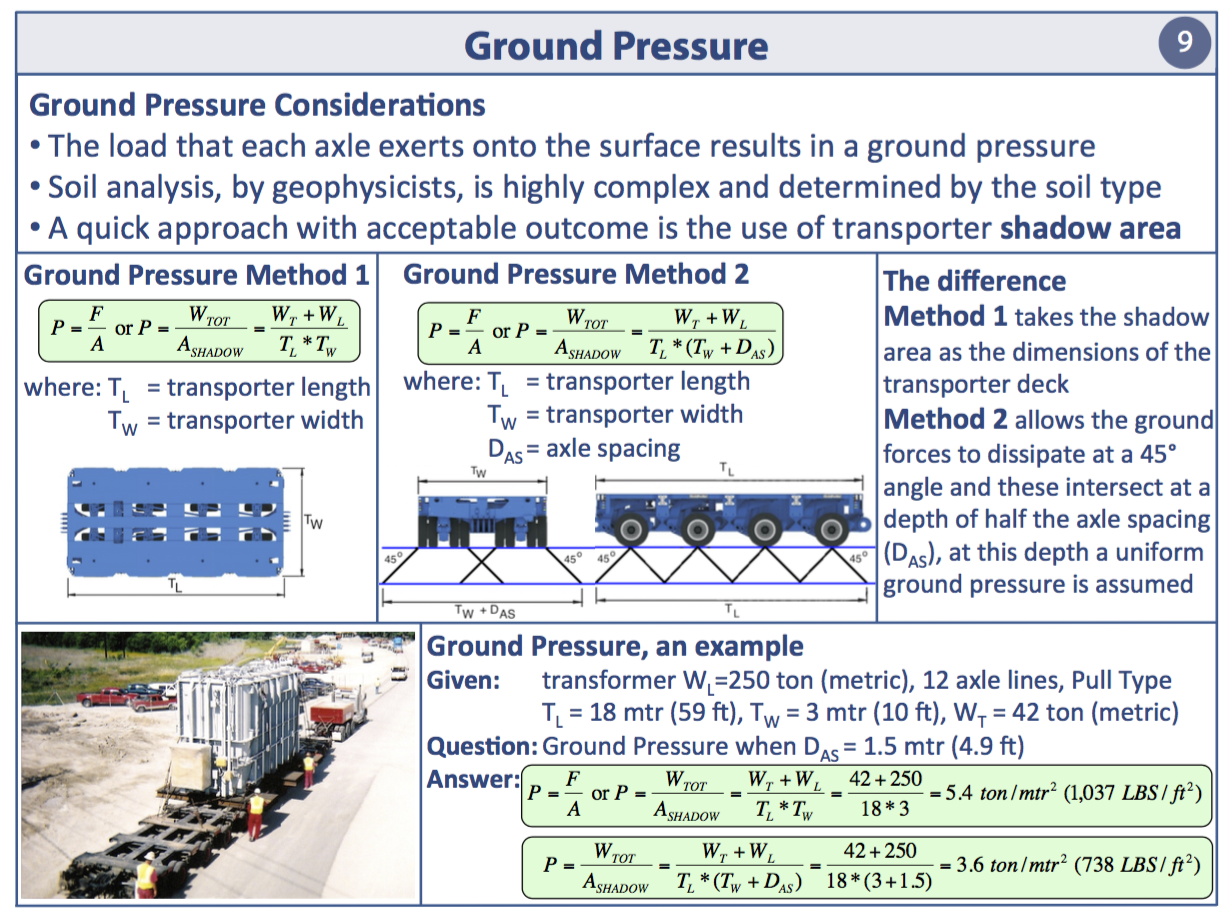
Panel 9 deals with ground pressure, arguably the most controversial topic in the Heavy Transport industry. This panel offers two easy methods of calculating ground pressure underneath a transporter. Both methods are an approach with acceptable outcomes and avoid that a full soil analysis by geophysicists has to be carried out. One method is a bit more conservative than the other, they both use the transporter “shadow area” as the base for the calculation.
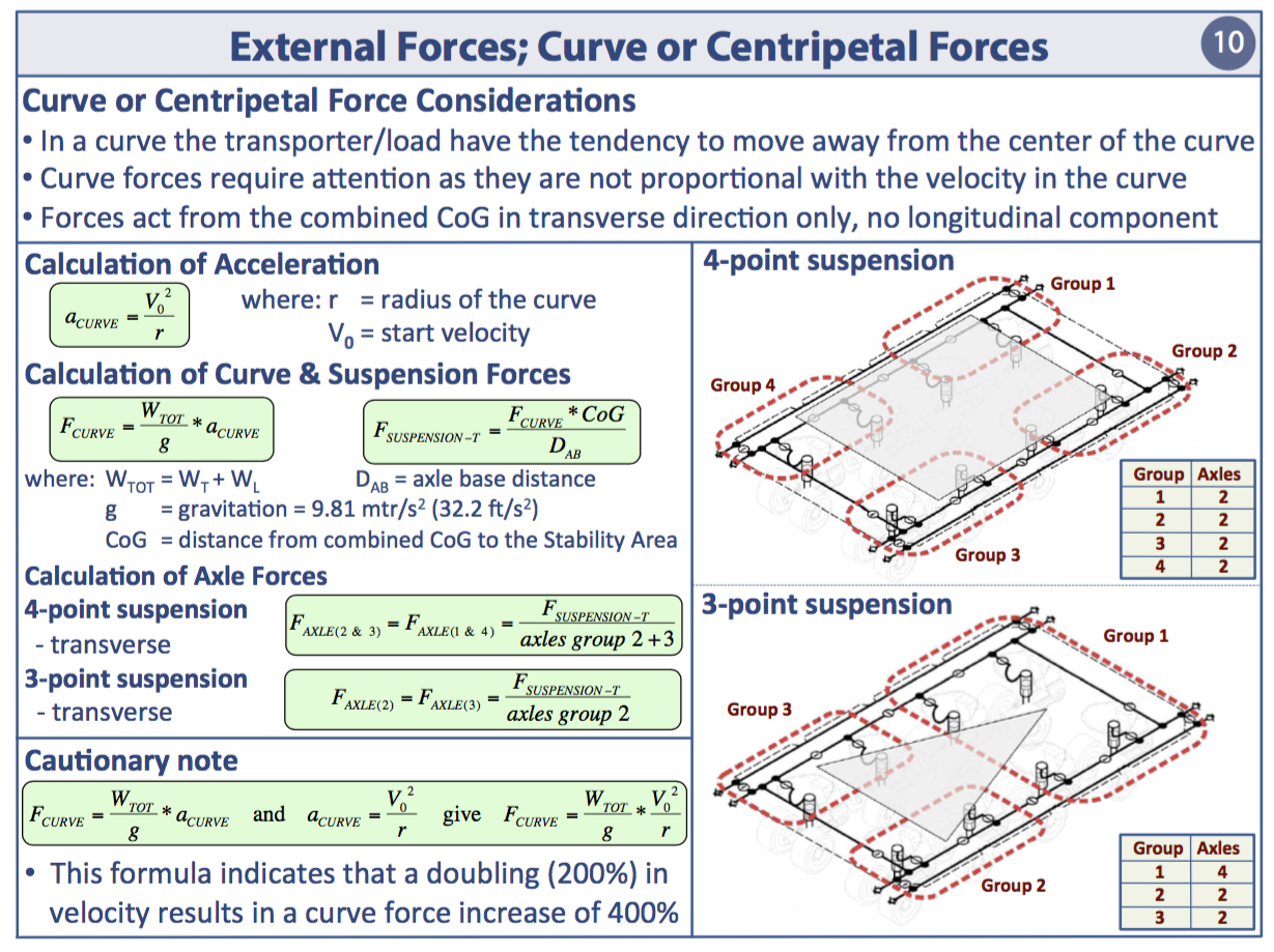
Panel 10 handles the first of 3 types of external forces, the curve or centripetal forces. The centripetal forces cause the transporter and load to have the tendency to move away from the center of the curve. The faster the transporter moves (higher speed), the higher these centripetal forces become. Centripetal forces can get out of control rather rapidly as they quadruple when the velocity doubles.
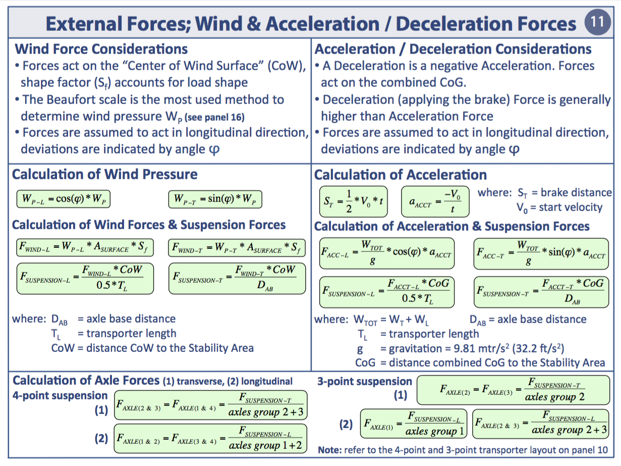
Panel 11 handles the second type of external forces, the wind and acceleration/deceleration forces. These forces are determined in a similar way although they act differently on the load. The deceleration forces, when applying the brakes or when making an emergency stop, are the most significant and therefore have the largest impact on transport stability. Still, the other forces cannot be neglected.
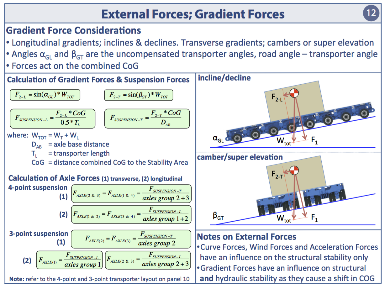
Panel 12 handles the gradient forces that act on a load when traveling on an incline/decline or when negotiating a road camber without the transporter being compensated for the angle. These uncompensated situations result in a longitudinal force (in case of an incline/decline) and a transverse force (in case of a road camber) that have an influence on the axle loads and ultimately on the stability of the transport.

Panel 13 is about lashing and securing. It shows how each lashing contributes in each direction given the angle it is applied at. This panel shows how much lashing is required to secure against the external forces from the preceding panels. The dunnage placed between the load and the transporter deck increases the friction which is taken into account as well. An added benefit is that correctly and sufficiently applied lashing reduces the combined Center of Gravity.
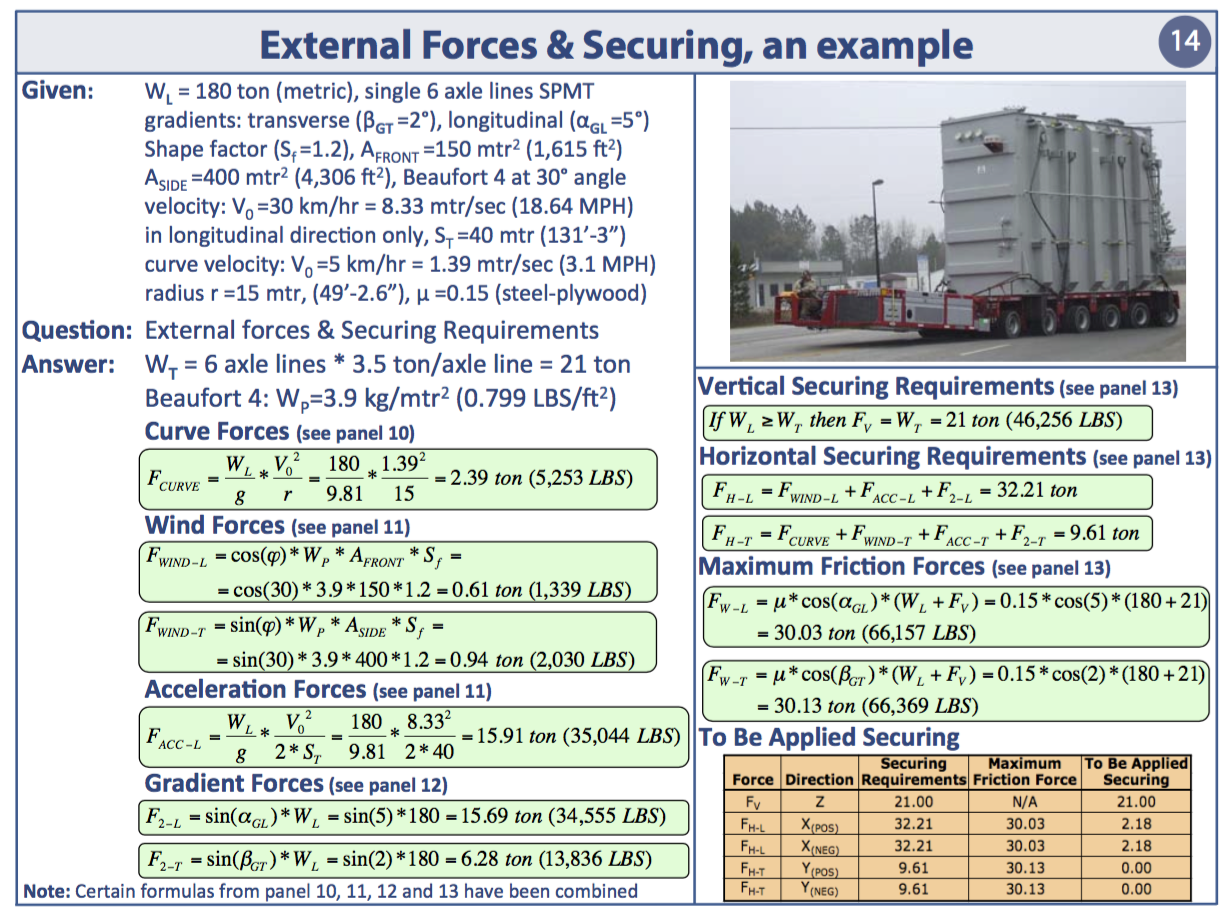
Panel 14 shows a complete lashing calculation using the information from the preceding panels. The external forces, wind, centripetal and acceleration/deceleration forces are all taken into account as well as the friction that is provided by the plywood placed between the load and the transporter deck. An easy to understand matrix indicates how much lashing is required in each direction under the given conditions.
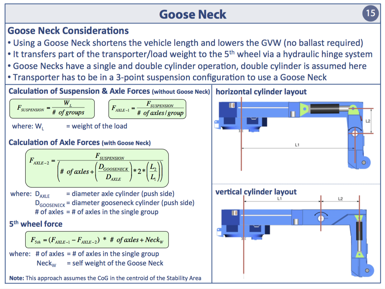
Panel 15 is about the application of a goose neck. Used by many, understood by few. This panel explains the difference between the two types of goose necks in existence. The goose neck transfers part of the load weight to the 5th wheel of the truck via a hydraulic hinge system, herewith eliminating the need for counterweight and resulting in a lower gross vehicle weight (GVW). This transfer of load results in a reduced axle load.
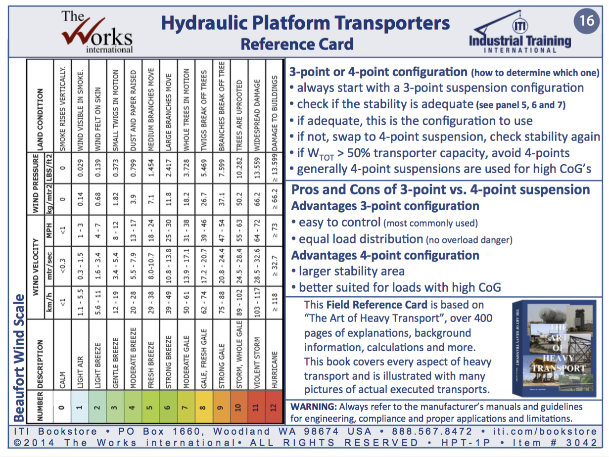
Panel 16 provides you with a Beaufort wind scale and a number of recommendation when deciding on a suspension configuration. It highlights the pros and cons of both the 3-point as well as the 4-point suspension configuration and recommends when to use which one. These recommendations are determined by the center of gravity (CoG) and the potential to overload the transporter.
Reference cards are not meant to replace back office or home office engineering or detailed calculations. Reference cards are mainly for a relatively quick decision in the field when there is a need for such a decision. Often a deviation from the planned work sequence has taken place and a verification is required to check if the new situation is still within the norm or margin. If the reference card indicates that this is indeed the case, the work can continue without any loss of time. If the reference card indicates that the new situation is too close for comfort, the engineering department needs to get involved. In such cases the field crew has at least explored the options before any down time is experienced.
|
Home
- Mission
- Services
- About Me
- Media
- Agenda
- Contact
- Site Map
Copyright © 2006 - 2019. The Works international. All Rights Reserved. |
The Works international is proud to be a member of
 |

